
The Dumb Doorbell Caper
- Mar 25
- 8 min read
It started innocently enough. The doorbell would occasionally ding, but wouldn't dong. Or, would it dong, but no ding? Matter of opinion perhaps. But, audiological semantics aside, the fact remained, it was on the blink. Then, one day, silence. No dong, no ding. And guests (Amazon drivers, mainly) being left annoyed that they had to hit the door to get our attention.
"No problem!" I announce. "It'll just need new batteries". I launched myself into the corner where the doorbell chime unit lives, dusted the cobwebs off it, and prised open the ageing, yellowing plastic cover. And... oh dear.

The batteries are certainly gone, I wasn't wrong. Their date stamps suggest they were best before 2018, so were probably installed a decade or more ago. And, ugh, just look at all that leakage. The good ship doorbell has well and truly bolted, I'm sure this bell was installed when the house was built, so it's well over 30 years old at this point.
Ok, so this is more than just a battery replacement - I don't have any C-cells in stock these days anyway, not since the children stopped needing them in their myriad toys.
I slapped in a temporary workaround and got thinking.

Replacements fell into three possibilities:
Embrace the future and get a Ring doorbell
Embrace the past and get a replacement battery chime unit
Do something halfway and integrate some sort of bell with Home Assistant
Option 1: Slightly amusingly both my wife and $child1 asked why not get a Ring doorbell. I spared them the lecture on how Amazon's privacy policy is so piss poor there's no way I'd buy an actual Ring. But, they had sort of a point, I do like "all this sort of stuff". UniFi make the Doorbell Lite, a ~£100 camera doorbell that will integrate into my existing UniFi Protect system; a bona-fide smart doorbell but without opening my street to Amazon's dubious eyes. The product was certainly promising. Ultimately, however, I decided against this. I already have a camera over the front door, and in all the years we've lived in this house, we've never lamented the lack of notifications on our phones when the doorbell goes.
Option 2: To my mild surprise, this idea turned out to be genuinely possible because Honeywell still make the exact, very-same doorbell. Why change what works! Or more likely, they couldn't figure out how to enshittify a bloomin' doorbell. I snapped one of these up anyway, as if nothing else I need to replace the battery-juice-covered chime of old.
Option 3: Now this starts to get interesting. I'm always up for any opportunity to slam in another ESPHome board with some interactions to real life. I'm sold. Let's see what we can do here.

The Honeywell door chime is a super simple circuit, basically batteries, a switch and a solenoid. There are two chime strips (which look like they've been nicked off a glockenspiel), when you press the bell push the solenoid thwacks one chime, then when you release the button, the solenoid relaxes and a little spring forces it to retract and hit the other chime. Ding Dong!
So it's the ideal job for an ESP board: Intercept the bell push and trigger the solenoid, all the while keeping Home Assistant in on the action.
System Design
Power
The doorbell itself holds 4 x 1.5V C cells, so nominally operates at 6V DC. The installation guide suggests it can also run from between 9 and 18V AC, if one was using a traditional bell transformer, but I don't have one of those.
After a bit of a segue into doing this the Wrong Way (see later) I had an epiphany: those C-cells are hardly going to be giving out 6V at the end of their life, yet the bell still happily ding dongs - I bet the bell will run off 5V just fine. And - presto - it does.
Driving the Bell
To keep the bell solenoid isolated from my circuit - and to cater for a possible eventuality where I find I need to run the bell from a different power supply to the ESP's 5V - I chose to put a relay between the ESP and the bell. The ESP can source 10mA from its GPO pins, but the relay needs 20mA, so I added a 2N3904 transistor (Icc of 200mA, more than enough for the relay) and didn't forget the freewheeling diode.
I wasn't sure that the 3.3V on board regulator could give me enough current for the relay, but the transistor also has the benefit of letting me run the relay from the 5V rail directly, so this wasn't a concern.
The Circuit

ESP Board: WEEMOS D1 Mini v3 (ESP8266 MCU)
C1: 1000uf 16V (for smoothing out any bumps from the solenoids)
D1: 1N4001
Q1: 2N3904
Relay: 5V coil @ 20mA, DPDT

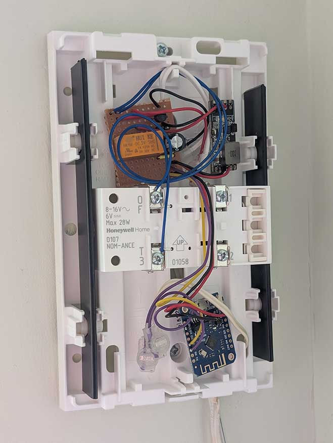
A small piece of stripboard was needed to hold the relay and the discrete components. It doubled up as a convenient junction board for the wiring, too.

Installation
Everything fitted neatly into the battery area of the chime unit. The wires to the bell push and the DC supply were attached to the circuit wiring with jelly crimps (which are cool).
That the purple wires are not contacting the "1" terminal - the screw just holds the wires neatly in place.
I also wrapped the DC supply wires through a ferrite bead for good measure; the DC wiring is a good few metres long and the ESP boards are sensitive to glitches picked up on long wires.
The two chime bars are also clearly visible in this photo.

The Wrong Way
I should take a moment here to admit to getting this all quite spectacularly wrong the first time I put it together. The photo above is the "version 2" design...
The bell power supply is meant to be 6V, but I didn't have one of those. It seemed to ding dong quite happily off an old 9V PSU I had lying about. So, that was picked.
The ESP board (I'm using a D1 Mini v3) needs 5V, but the ESP8266 itself runs at 3.3V via an on-board regulator. I thought "I don't want to be regulating the voltage twice, from 9V to 5V to 3.3V", so I got a 5-30V to 3.3V DC regulator board and hooked that up to the D1's 3.3V power pin. This power module is visible in the prototyping photo above, if you look closely.
Because I had "plenty" of current available from the 3.3V supply, I thought I could run the relay off it too, so got hold of a relay with a 3V coil.
Then, there wasn't room to fit the ESP, relay and power board in the same battery compartment in the chime unit, so I put the ESP board on the end of some long wires.
OH DEAR BIG MISTAKE(s)! Something about this set up rendered the ESP completely unstable and it kept being rebooted by all manner of watchdog timers. It was probably the power supply, something about the 9V supply was noisy, or the 3.3V external board was unstable, or perhaps connecting power into the 3.3V pin on the D1 board bypasses something important. Whatever the reason, the whole thing was so unstable I had to pull it out (or restore the sticker on the bell push!)
So I redesigned it entirely. Finding out that the bell runs from 5V just fine, using a USB charger to power it - as I do with all my other ESP boards, which work really well. Keeping all cables super short, even reducing unnecessarily long stripboard tracks. Ensuring the smoothing cap is really close to the D1 board. Fortunately, this seems to have done the trick, and the ESP no longer reboots all the time. Phew. Lesson learned.
ESP Functionality
The ESPHome integration for my new smartish dumb doorbell will delivery bell push notifications to Home Assistant. But this felt somewhat insufficient. I could do more.
Pet Peeve: Quick Dings
It's always annoyed me when people press the bell push so quickly they only give half a ding dong. Or, hammer on the bell push repeatedly, giving a "ding ding ding dong". Nah, fuck that behaviour. I can use the ESP to deliver a constantly-spaced "ding dong"! A simple little script can do it, and it turns out that 0.5s between the ding and the dong sounds about right to me.
# Output to drive bell via relay
output:
  - platform: gpio
    pin: GPIO4
    id: bell_relay

# Automate a relay click to ring the bell
script:
  - id: ring_bell
    then:
      - output.turn_on: bell_relay
      - delay: 0.5s
      - output.turn_off: bell_relay
Bell Push
Easy - define the bell push as an input. Except, I want it visible in Home Assistant, so define it as a binary_sensor. My circuit needs the internal pull-up enabled, and because the bell push shorts the input pin to ground, turning it off, when the bell is pushed, the pin needs to be inverted. And we'll debounce the pin for good measure, too.
Then I simply need to make the bell push trigger the script.
# Input to receive button presses
binary_sensor:
  - platform: gpio
    pin:
      number: GPIO5
      mode:
        input: true
        pullup: true
      inverted: true
    name: "Bell Push"
    icon: "mdi:doorbell"
    filters:
      - delayed_off: 100ms
    on_press:
      then:
        - script.execute: ring_bell
The binary_sensor automatically appears in Home Assistant. For neatness I also specified the icon and sensor name in the ESPHome configuration.

Remote Control
Because I'm a monster at going too far for no reason, I thought it'd be fun to be able to trigger the bell ding dong from Home Assistant. Why not?! Momentary actions are conveyed through ESPHome via buttons, and the template button is a virtual construct that will appear in Home Assistant without needing to physically exist as a GPIO pin on the ESP.
# HA Button to trigger a bell ring
button:
  - platform: template
    name: "Ring Bell"
    icon: "mdi:bell-ring"
    on_press:
      - script.execute: ring_bell
And I also thought "hmm, what about also adding a switch so I can disable the bell from sounding!" Boolean actions are conveyed through ESPHome via switches, and again the template switch is a virtual construct that appears in Home Assistant without needing a physical pin on the ESP.
Optimistic mode means the switch state change is immediately reflected back to Home Assistant (although this may not be needed with a template switch, perhaps more designed for physical outputs), and I use restore_mode to ensure the bell comes up enabled when the ESP boots.
# Switch to enable/disable the bell
switch:
  - platform: template
    id: bell_enabled
    name: "Bell Enabled"
    icon: "mdi:bell-check"
    optimistic: true
    restore_mode: ALWAYS_ON
With the virtual switch given an ID, then a condition is added to the binary_sensor to check this before triggering the ring_bell script:
binary_sensor:
  - platform: gpio
    ...
    on_press:
      then:
        - if:
            condition:
               switch.is_on: bell_enabled
            then:
              - script.execute: ring_bell
The full ESPHome (sensor) configuration
I added a couple of status sensors for monitoring and information purposes. The final ESPHome configuration reads as follows:
# Input to receive button presses
# GPIO5 = D1 (purple wire)
binary_sensor:
  - platform: gpio
    pin:
      number: GPIO5
      mode:
        input: true
        pullup: true
      inverted: true
    name: "Bell Push"
    icon: "mdi:doorbell"
    filters:
      - delayed_off: 100ms
    on_press:
      then:
        - if:
            condition:
               switch.is_on: bell_enabled
            then:
              - script.execute: ring_bell

# Output to drive bell via relay
# (Output entries are not visible to HA)
# GPIO4 = D2 (yellow wire)
output:
  - platform: gpio
    pin: GPIO4
    id: bell_relay

# Automate a relay click to ring the bell
# Script will only run once at a time by default
script:
  - id: ring_bell
    then:
      - output.turn_on: bell_relay
      - delay: 0.5s
      - output.turn_off: bell_relay

# Switch to enable/disable the bell
switch:
  - platform: template
    id: bell_enabled
    name: "Bell Enabled"
    icon: "mdi:bell-check"
    optimistic: true
    restore_mode: ALWAYS_ON

# HA Button to trigger a bell ring
button:
  - platform: template
    name: "Ring Bell"
    icon: "mdi:bell-ring"
    on_press:
      - script.execute: ring_bell

# Numeric diagnostics
sensor:
  - platform: uptime
    name: "Uptime Sensor"

# String diagnostics
text_sensor:
  - platform: debug
    reset_reason:
      name: "Reset Reason"
Epilogue
And there we have it - a nicely integrated dumb doorbell!
With only a small amount of messing it up in the middle of the adventure.
To be honest with you, I have yet to find a use for any of the Home Assistant integration; as I mentioned before, we never missed not getting bell push notifications. But I'm sure I'll find something to do with this event eventually. Build it (i.e. integrate it) and they will come (find a use)!


Comments